INSTRUVIO

Sample CPD module

RainSafe Tank Installation

How to unload, excavate, line, build and backfill a RainSafe stormwater attenuation tank.

  • 45 steps
  • 20 questions
  • 16/20 to pass
  • 30 minutes

Step 1 of 65

A completed RainSafe tank under a finished car park, shown in cutaway

Before you start

Welcome

  • Congratulations on selecting RainSafe for your stormwater management system.
  • Your tank has been designed to provide the required storage volume, design flow-rate, loading capacities, maintainability and primary water requirements.
  • This module takes about 30 minutes and follows the installation from the delivery lorry to the final geotextile. There are twenty questions along the way, and you need 16 out of 20 to pass.
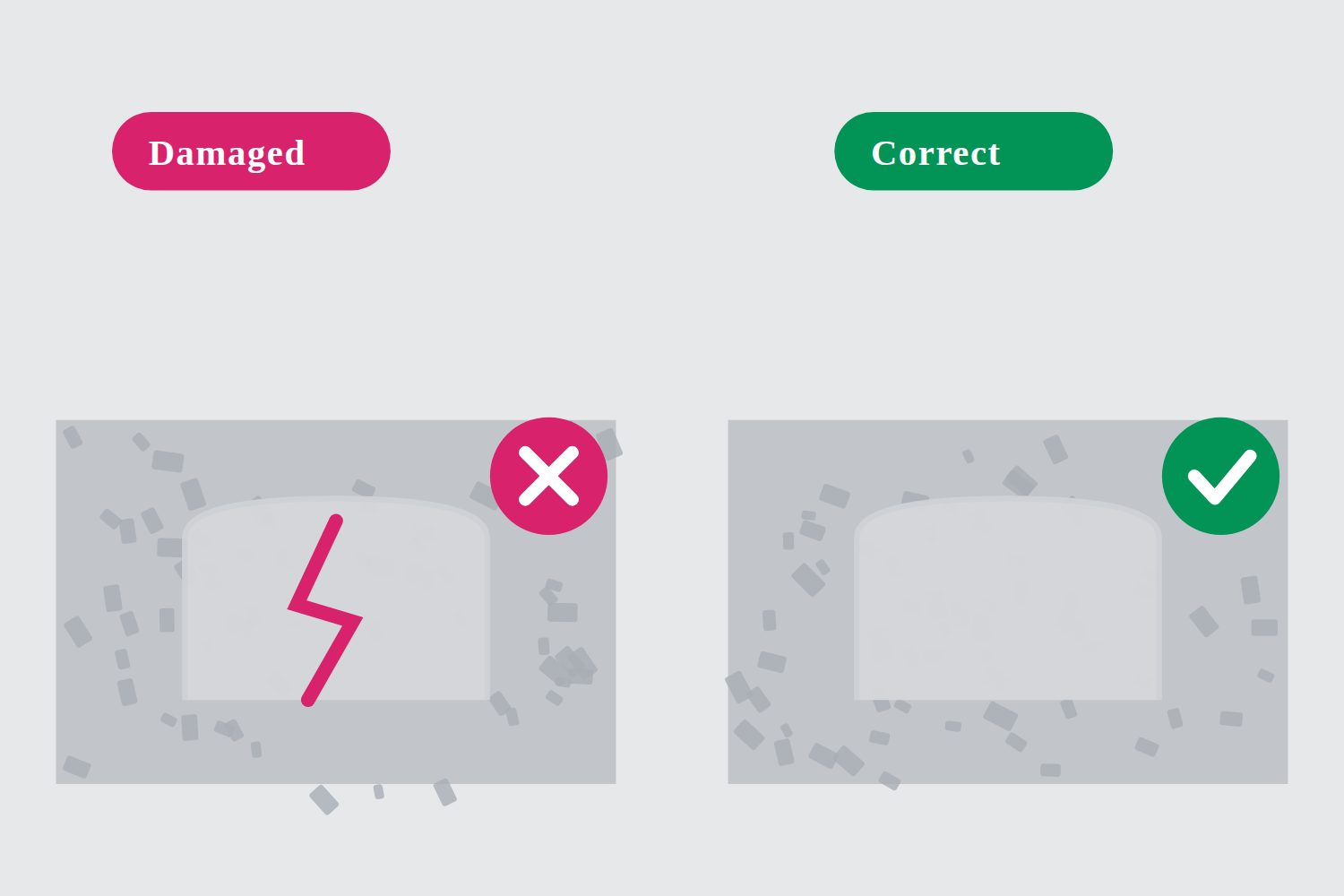
A cracked chamber beside an intact one

Before you start

Why the guidelines matter

  • Failure to adhere to these guidelines may result in damage to the chambers, and in inadequate hydraulic or structural performance of the tank.
  • The tank is buried. Once the stone and the surface are on top of it, nothing inside is visible and nothing is easy to reach.
  • Remediation after backfilling has been carried out is costly and time-consuming.

Every mistake on this job is cheap to fix before the stone goes in, and expensive afterwards.
A site team gathered around a drawing, one signing a record sheet

Before you start

Who needs to know this

  • For the requirements to be met and the tank to be certified, all installers and machine operators involved in the installation must be familiar with the guidelines.
  • They must agree to strictly follow the instructions, and provide a record of having done so.
  • That record is part of the certification of the tank, not a formality to be caught up on later.
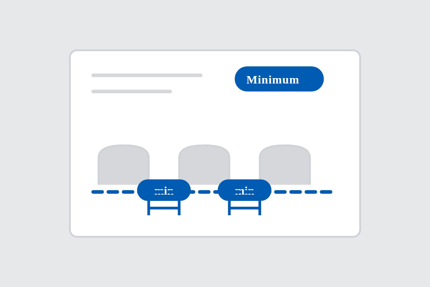
A drawing marked with minimum dimensions

Before you start

These are minimum requirements

  • These guidelines are general, and provide the minimum requirements for correct installation of your system.
  • The project drawings may ask for more than the minimum. Where they do, the drawings govern.
  • Any deviation from the steps and measures detailed in this guide, whether because of site-specific constraints or any other requirement, must be approved by CubicM3.

A site constraint is a reason to ring CubicM3, not a reason to improvise.

A CubicM3 representative talking a crew through the guidelines on site

Before you start

The pre-installation briefing

  • A CubicM3 or RainSafe representative will provide a pre-installation briefing to run through these guidelines.
  • The briefing is where to raise anything the drawings do not cover: awkward levels, restricted access, unusual traffic loading, or a sequence that does not suit the programme.
  • Bring questions to it. It is much cheaper than finding the answer halfway through backfilling.

Before you start · Question 1 of 20

When does putting a mistake right become costly and time-consuming?

Before you start · Question 2 of 20

Site constraints mean you cannot achieve the spacing shown on the drawings. What do you do?

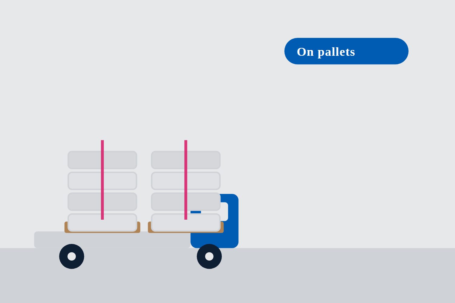
A flatbed lorry carrying palletised stacks of RainSafe chambers

Unloading the chambers

Delivery on pallets

  • Your RainSafe chambers will arrive at the site on pallets.
  • The chambers have been designed to pack efficiently, to minimise storage space requirements and to protect the chambers in transit and in the stockpile.
  • They should remain on their pallets until they are ready for installation.
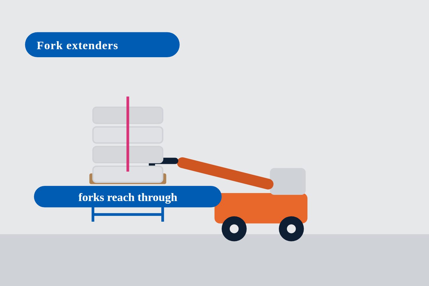
A telehandler with fork extenders lifting a tall pallet of chambers

Unloading the chambers

Unloading the pallets

  • Pallets should be unloaded carefully, using fork-extenders where necessary.
  • The stacks are deeper than a standard set of forks. Without extenders the load is carried on the tips, which is how pallets get dropped.
  • Banding straps should only be removed just before installation.

The straps are what holds a tall stack together. Cut them early and the stack is no longer a stack.

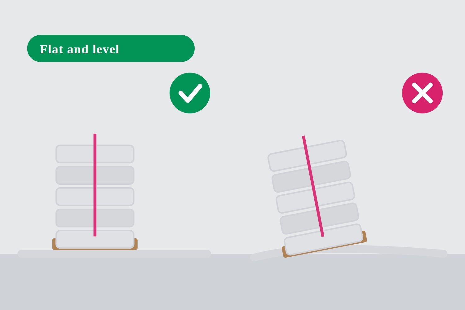
A pallet stack standing square on level ground beside one leaning on soft ground

Unloading the chambers

Tall, heavy and easy to topple

  • The palletised stacks are tall and heavy.
  • The pallets should be placed on flat, level ground to avoid the risk of toppling. Soft or sloping ground under one corner is enough to start a stack moving.
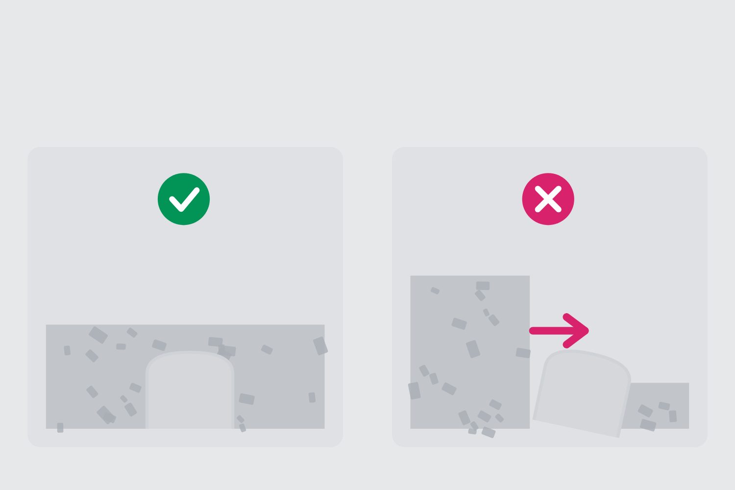
  • When unloading chambers, they should be lifted off the stack carefully by at least two operatives.
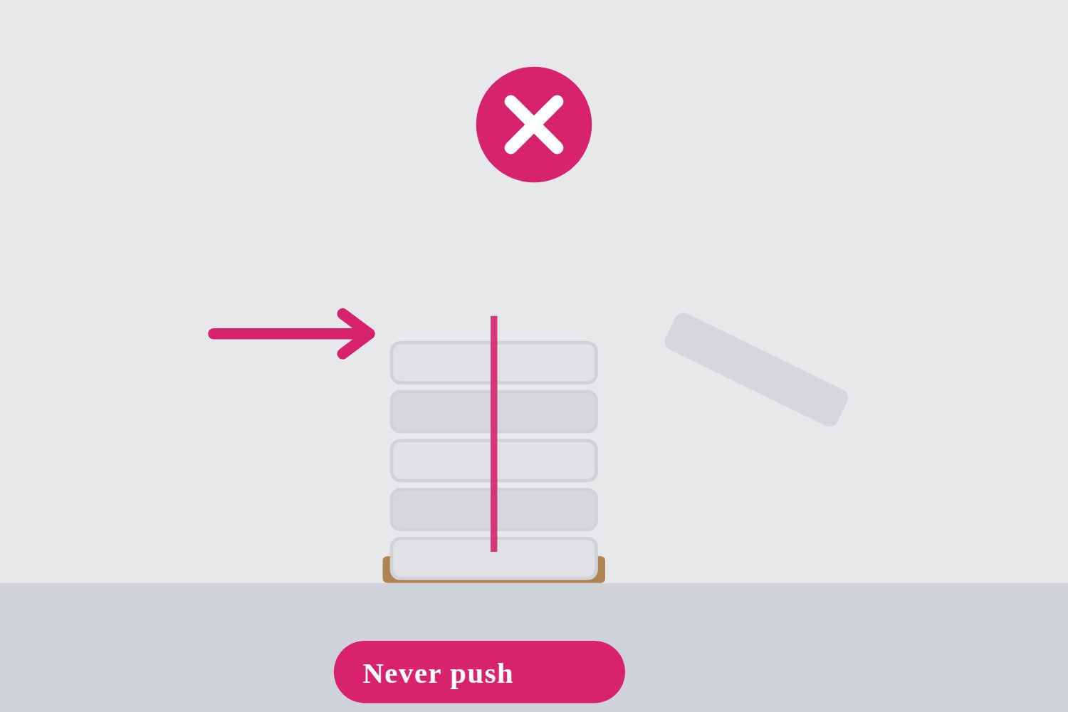
A crossed-out illustration of a chamber being pushed off the top of a stack

Unloading the chambers

Never push, never topple

  • The chambers should never be pushed off the top of the stack.
  • Stacks should never be pushed over to make unloading quicker.
  • Doing either could cause serious injury or even death, and result in significant damage to the chambers.

Chambers are light enough to lift and large enough to kill someone when they fall from height.

Unloading the chambers · Question 3 of 20

When should the banding straps come off a pallet of chambers?

Unloading the chambers · Question 4 of 20

How should a chamber be taken off the top of a stack?

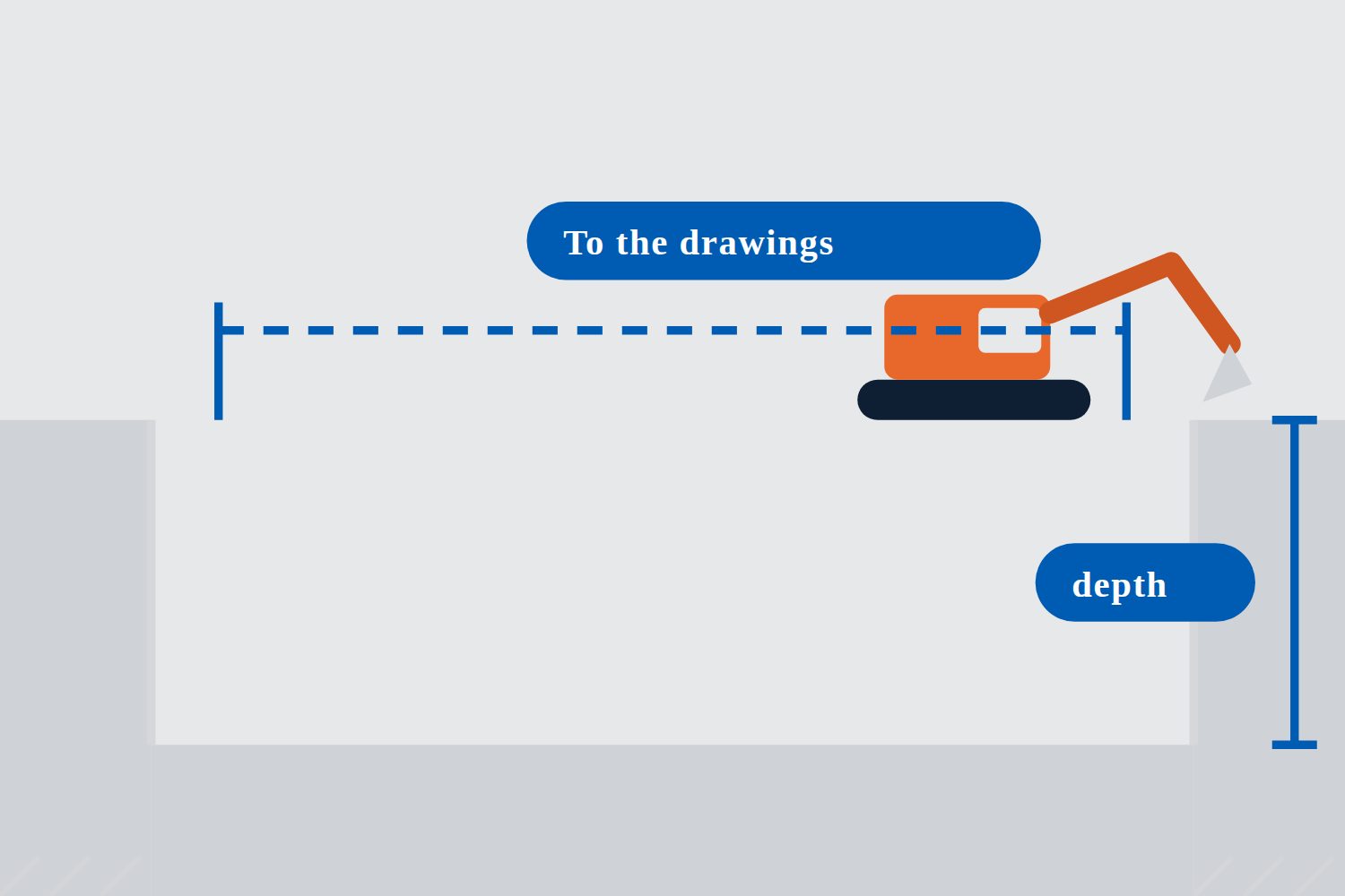
An excavator forming a rectangular tank bed, with level pegs set out

Tank excavation

Excavate to the drawings

  • Excavate the tank bed to the dimensions and levels shown in the drawings, and prepare the sub-grade.
  • The dimensions include the working space around the rows, not just the footprint of the chambers themselves.
  • Levels matter as much as plan size: the whole tank is built off this surface.
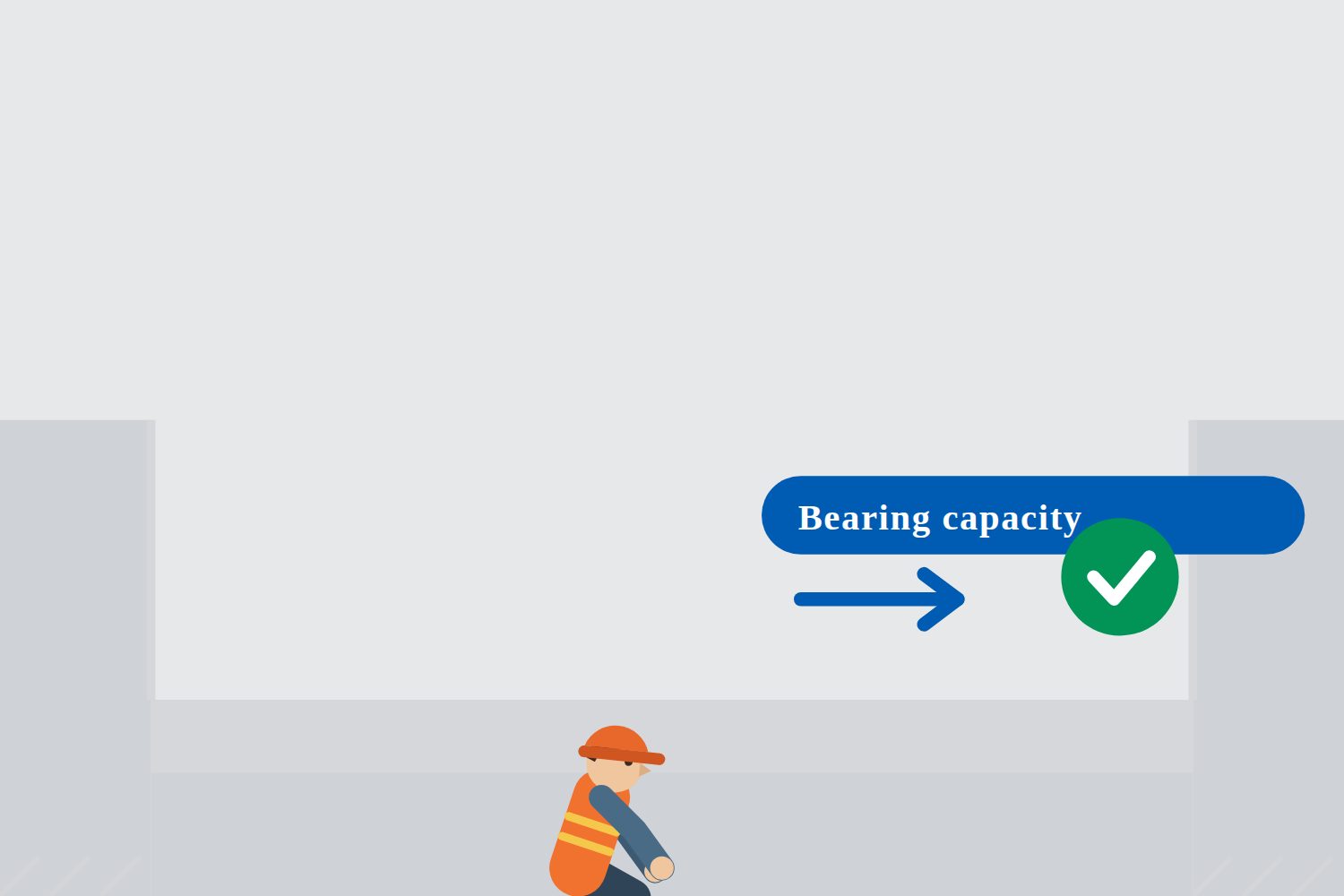
An engineer testing the bearing capacity of an excavated formation

Tank excavation

Check the sub-grade

  • The quality and bearing capacity of the sub-grade must be inspected and confirmed to meet design requirements.
  • What counts as adequate depends on the expected traffic loading above the tank and on the total cover depth over it.
  • Refer to the RainSafe CSTB-ATec document for detailed guidance.

Inspected and confirmed, not assumed. The whole structure is carried by this formation.

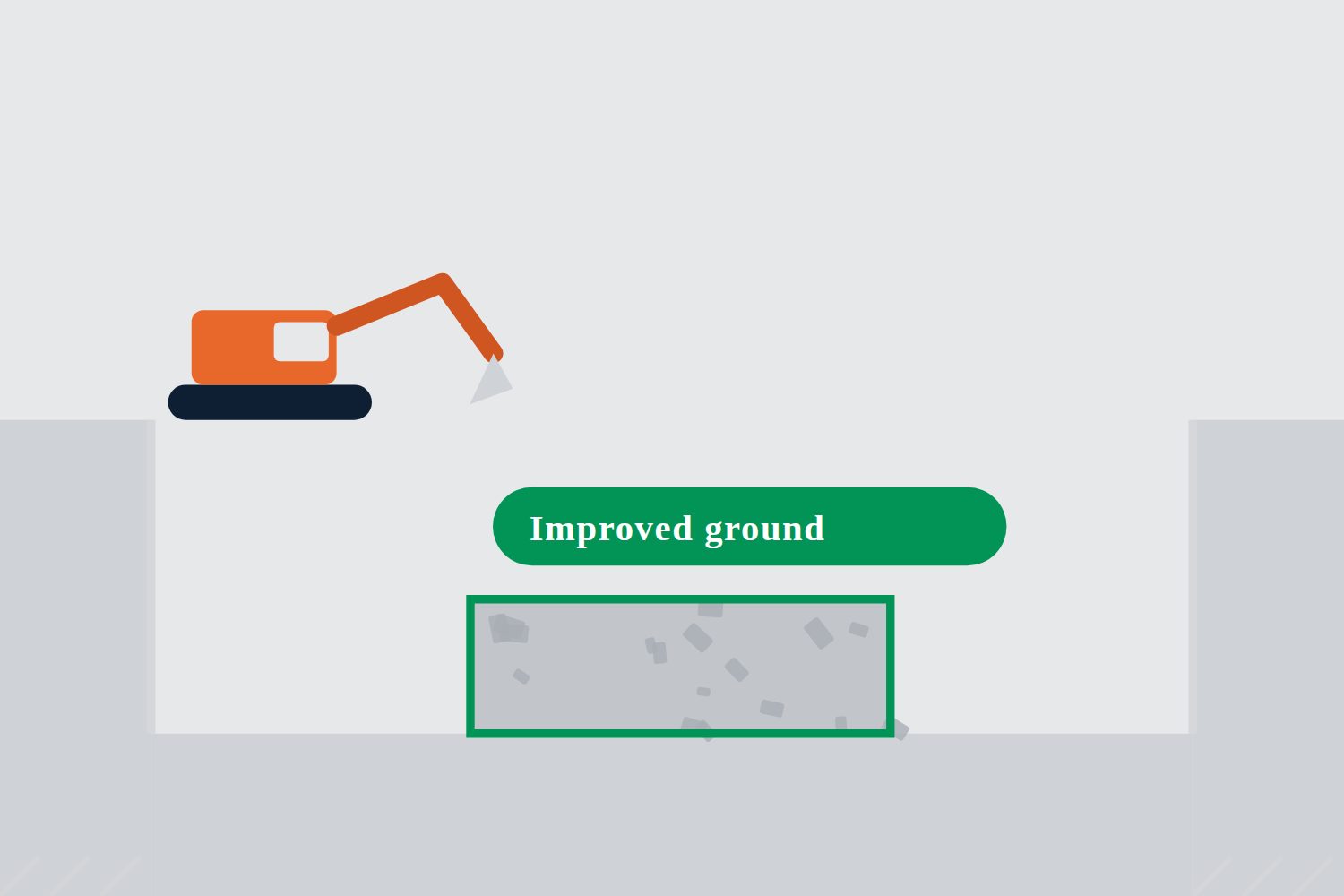
A soft patch of formation being dug out and replaced with compacted stone

Tank excavation

Ground improvement

  • At this stage, ground improvement measures should be taken where necessary.
  • This is the moment for it. Once the liner and the bedding stone are down, improving the ground underneath means taking the tank back apart.
  • What is required will come from the design: the inspection of the formation decides whether it is needed.
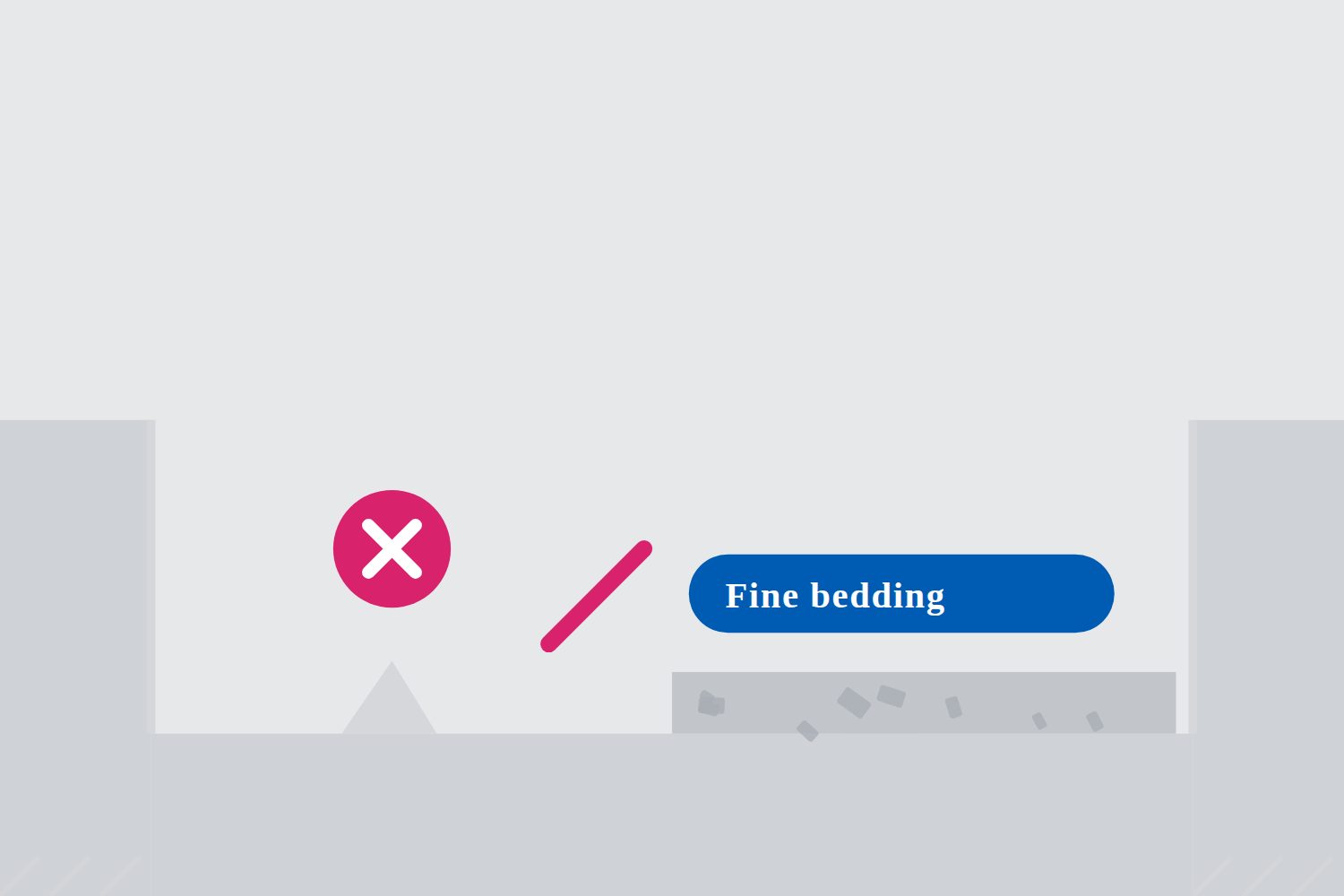
A sharp stone being lifted out of the formation, with fine bedding material alongside

Tank excavation

Protect the liner

  • Any protruding sharp objects should be removed to protect the tank liner.
  • Rock, old services, reinforcement and broken concrete all puncture a liner under load, and the puncture is not found until the tank is in service.
  • If necessary, a protective layer of fine bedding material should be placed prior to installation of the liner.

Tank excavation · Question 5 of 20

Which document gives detailed guidance on sub-grade quality and bearing capacity?

Tank excavation · Question 6 of 20

Why are protruding sharp objects removed from the excavation?

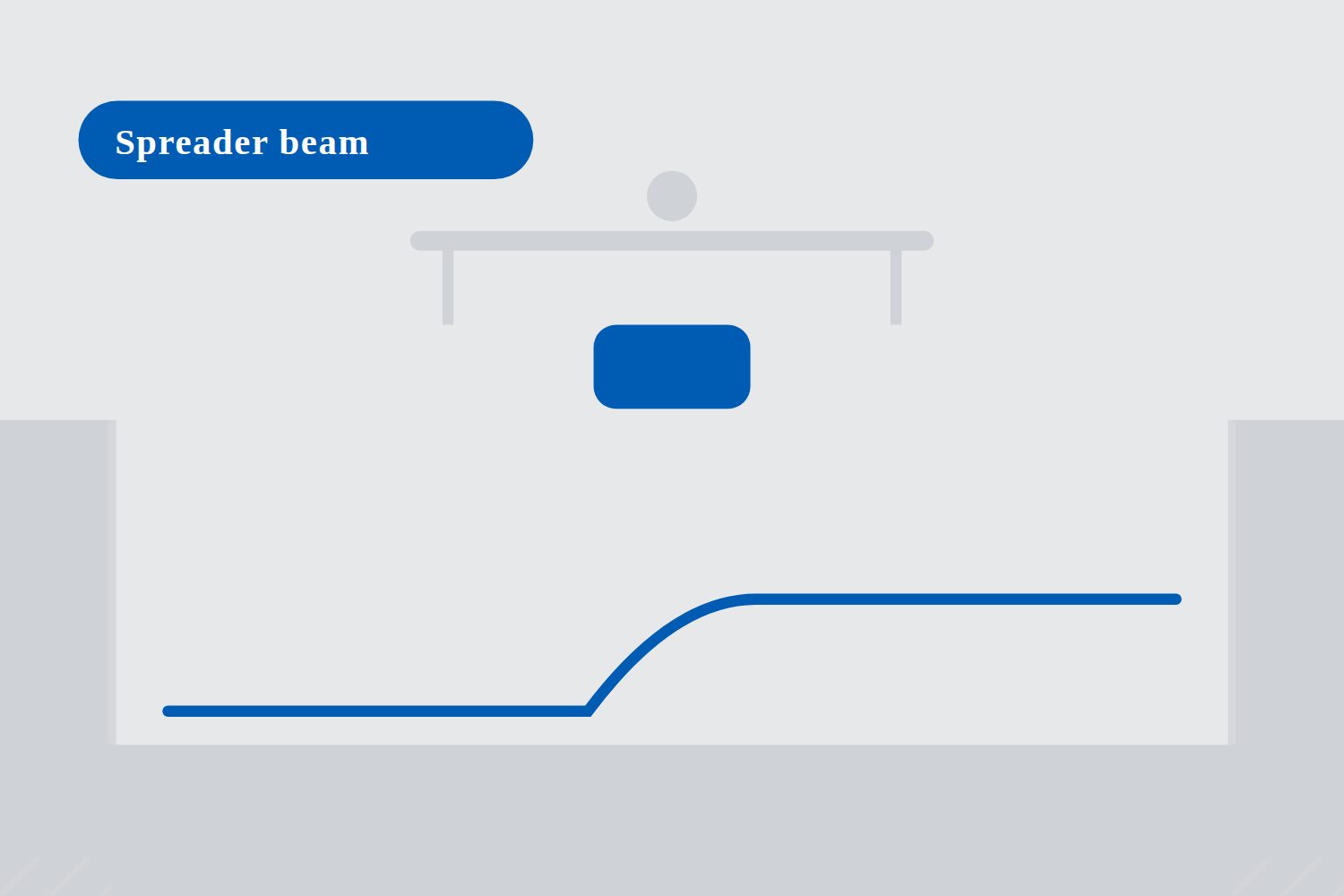
A roll of liner being unrolled across a tank bed from a spreader beam

Placing the tank liner

Laying the liner

  • Place a non-woven geotextile or impermeable liner over the prepared tank bed, as specified for your tank.
  • Use of a spreader beam is highly recommended. It keeps the roll level and takes the drag off the material as it comes off.
  • Dragging a liner across a formation is how it picks up damage and how it ends up out of position.
A flat lapped joint beside a wrinkled one marked with a cross

Placing the tank liner

Wrinkles and overlaps

  • Avoid wrinkles, and ensure minimum joint overlaps are maintained.
  • A wrinkle is a fold that concentrates load and gives stone a point to work against.
  • An overlap that has crept below the minimum is a joint that will open under fill.

Flat and fully lapped before any stone goes on. It cannot be corrected later.

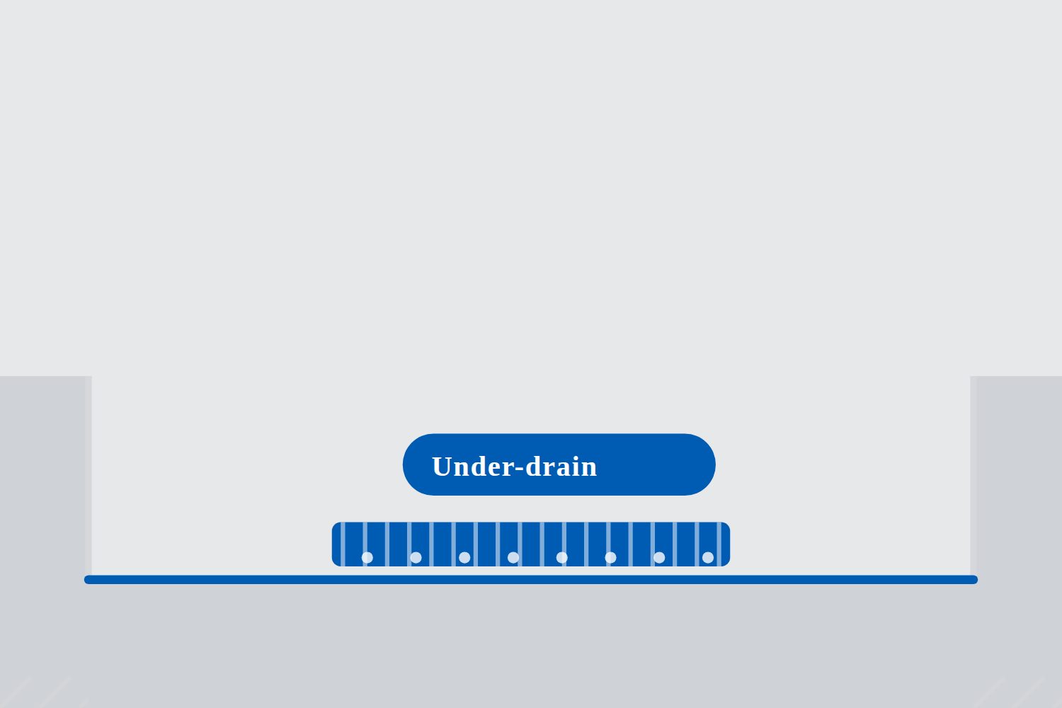
A perforated under-drain laid along the base of the lined tank

Placing the tank liner

Under-drains

  • Install the under-drain or drains, as per the tank design.
  • Position, fall and connection all come from the design drawings for your tank.
  • Note where they run. They are the one thing in the base that the bedding stone and the plant placing it can damage.

Placing the tank liner · Question 7 of 20

What is highly recommended when placing the tank liner?

Placing the tank liner · Question 8 of 20

Which pair of defects must be avoided in the liner?

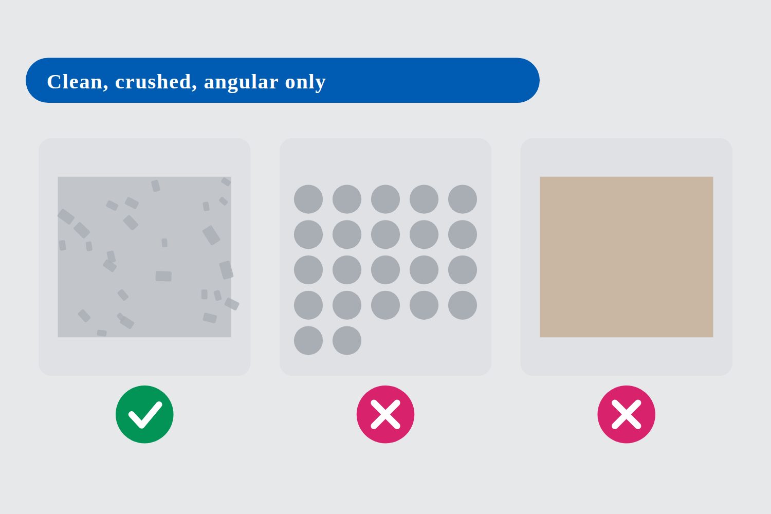
Clean angular stone beside rounded and dusty material marked with crosses

Placing the bedding stone

Only one kind of stone

  • Only clean, crushed, angular stone may be used within the tank.
  • It should conform to Clause 505 Type B, or Remblai 20-40 specification.
  • Rounded stone rolls instead of locking. Dirty or fine material blocks the voids the tank relies on to store and move water.

Clean, crushed, angular. Anything else changes both the structure and the storage.

Bedding stone being spread and compacted across the lined tank bed

Placing the bedding stone

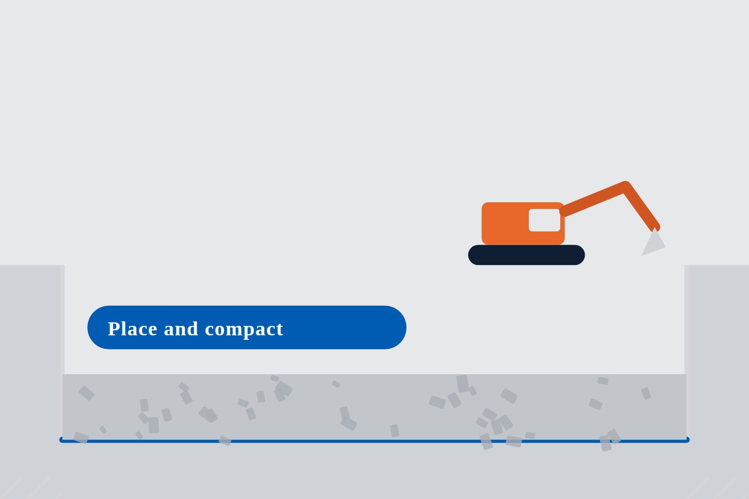
Place and compact

  • Place and compact the bedding stone.
  • This is the layer the chambers sit on, so it is compacted before any chamber is set out on it.
  • Work it up evenly across the bed rather than in one corner at a time.
A staff measuring the depth of the bedding layer against a marked level

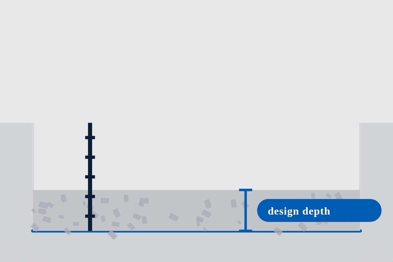
Placing the bedding stone

Depth to the design

  • The depth of bedding stone must be as per the design drawings, and should reach the minimum depth.
  • Check it across the bed, not at one point. A bed that is right at the edges and shallow in the middle is not a level bed.
  • If the formation needed improvement, confirm the depth again over the improved ground.
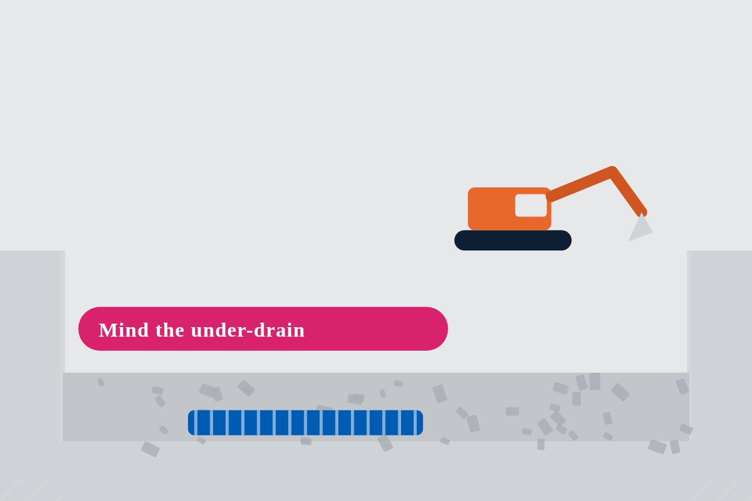
A tracked machine placing bedding stone, keeping clear of a marked under-drain

Placing the bedding stone

Equipment and under-drains

  • There is no restriction on the type of equipment used for the placement of the bedding stone.
  • The restriction on plant comes later, once the chambers are in and the fill is going on around them.
  • However, take care to avoid crushing or otherwise damaging the under-drain or drains.

Placing the bedding stone · Question 9 of 20

Which stone may be used within the tank?

Placing the bedding stone · Question 10 of 20

What restricts the equipment used to place the bedding stone?

Chamber row positions marked out in line on the bedding stone

The Separator Row

Mark out the rows

  • Mark chamber row positions out clearly on the bedding stone.
  • Marking every row before the first chamber lands is what keeps the spacing between rows right across the whole tank.
  • It is far easier to correct a line on the stone than a row of connected chambers.
A plan of the tank with the Separator Rows highlighted against the inlet manholes

The Separator Row

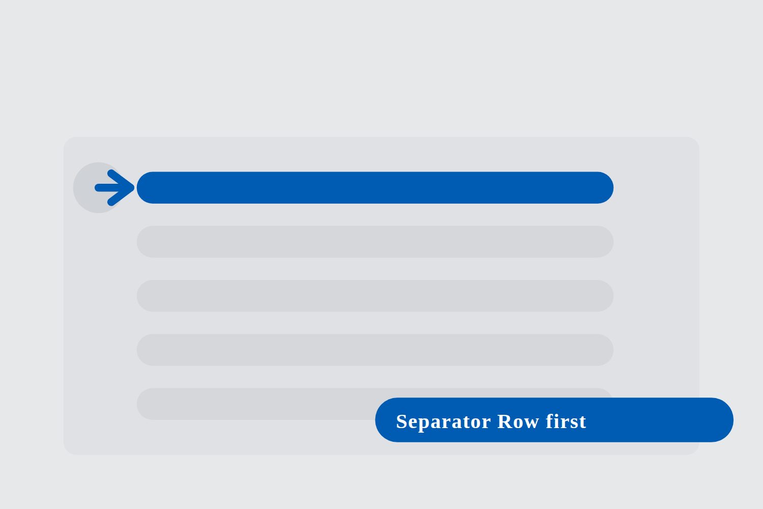
Start with the Separator Rows

  • Installation of the RainSafe chambers begins with the Separator Rows, which connect to the inlet manholes.
  • The Separator Row takes the incoming flow, so it sets the position of everything built off it.
  • Build these first and the rest of the tank follows from them.
A strip of woven geotextile laid along the marked line of the Separator Row

The Separator Row

The woven geotextile bed

  • The woven geotextile bed is laid out in the correct position, along the line marked for the Separator Row.
  • Woven, not non-woven: this is the strip the Separator Row is built on, and it is specified for strength.
  • Position it against the marks before any chamber goes on it.
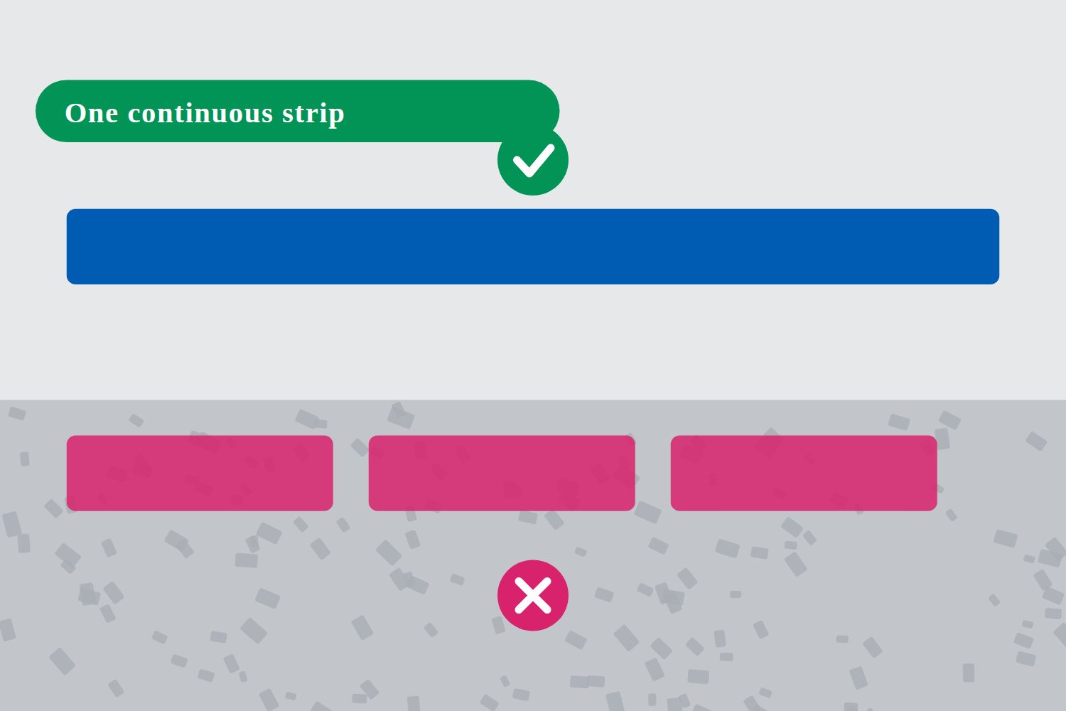
A single continuous strip running the full length of a row

The Separator Row

Continuous, flat, no wrinkles

  • A continuous strip must be provided for the full length of the Separator Row.
  • This must be flat and free of wrinkles.
  • Continuous means exactly that: not a run of short pieces laid end to end under the chambers.
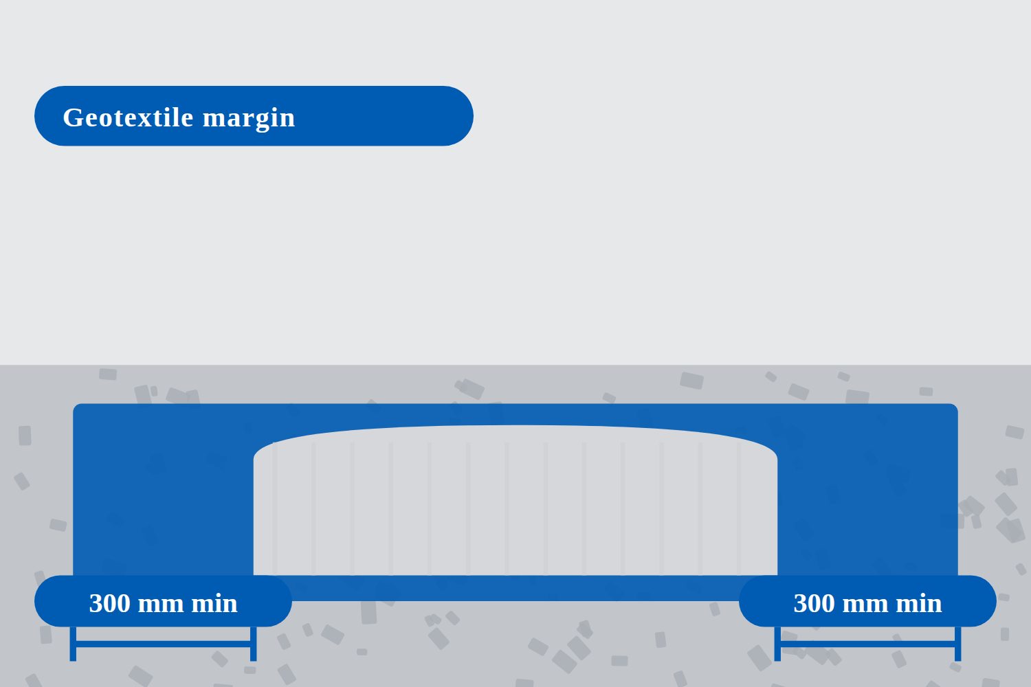
The geotextile extending a marked 300 millimetres past the edge of a chamber

The Separator Row

The 300 millimetre margin

  • Sufficient length and width must be provided to ensure the geotextile extends a minimum of 300 millimetres beyond the side edges and ends of the Separator Row chambers and end caps.
  • The stone placed on that margin later is what holds the geotextile in place.
  • That is what allows the Separator Row to be jetted and maintained over the life of the tank without pulling the bed out from under it.

The 300 millimetre margin is a maintenance detail, not a tolerance. It is why the tank can be cleaned.

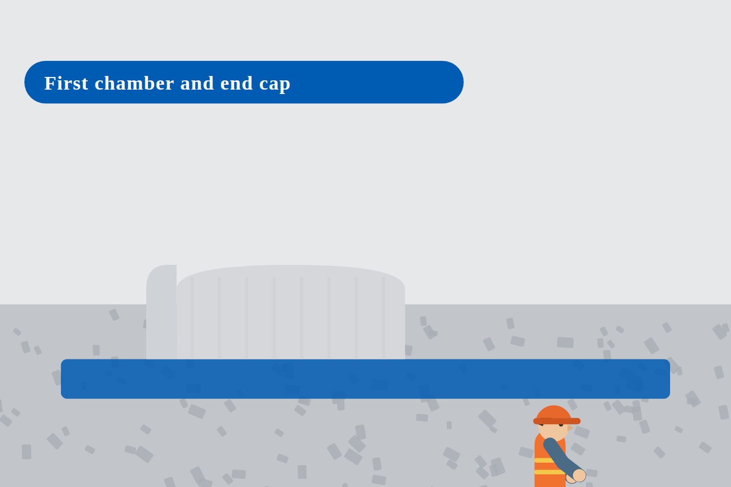
The first chamber of a row set down with its end cap in place

The Separator Row

First chamber and end cap

  • The first chamber and end cap of the Separator Row are then placed in position.
  • Set them to the marks. The whole row, and the rows built off it, follow this first unit.
  • Check the position before connecting anything to it.
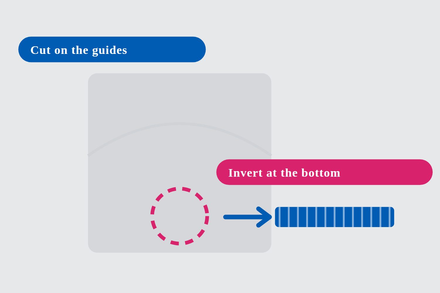
An end cap being cut on its moulded guide with a reciprocating saw

The Separator Row

Cutting the inlet

  • Following the cutting guides on the end cap, cut a hole for the inlet pipe using a reciprocating saw.
  • The inlet hole invert should always be at the bottom of the end cap.
  • Insert the corrugated inlet pipe, ensuring a minimum of 300 millimetres protrudes into the chamber.

Invert at the bottom, and 300 millimetres of pipe inside the chamber.

Two chambers being joined, large corrugation over small, with locating buttons aligned

The Separator Row

Building out the row

  • Build out the Separator Row, following the direction guides shown on the tops of the chambers.
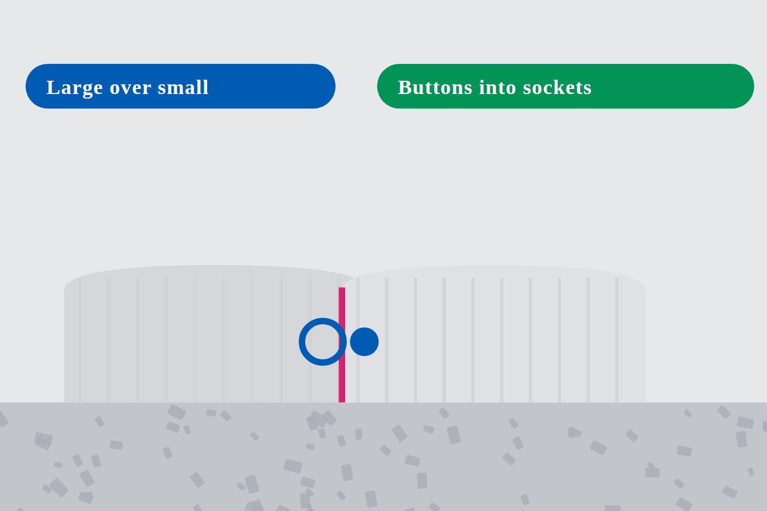
  • Fit the large end-corrugations over the smaller end-corrugations on the other end of the chamber.
  • To ensure a firm connection, slot the locating buttons into the corresponding sockets. Repeat this for the entire length of each row.
An end cap cut at the top to receive the overflow bypass pipe

The Separator Row

The overflow bypass end

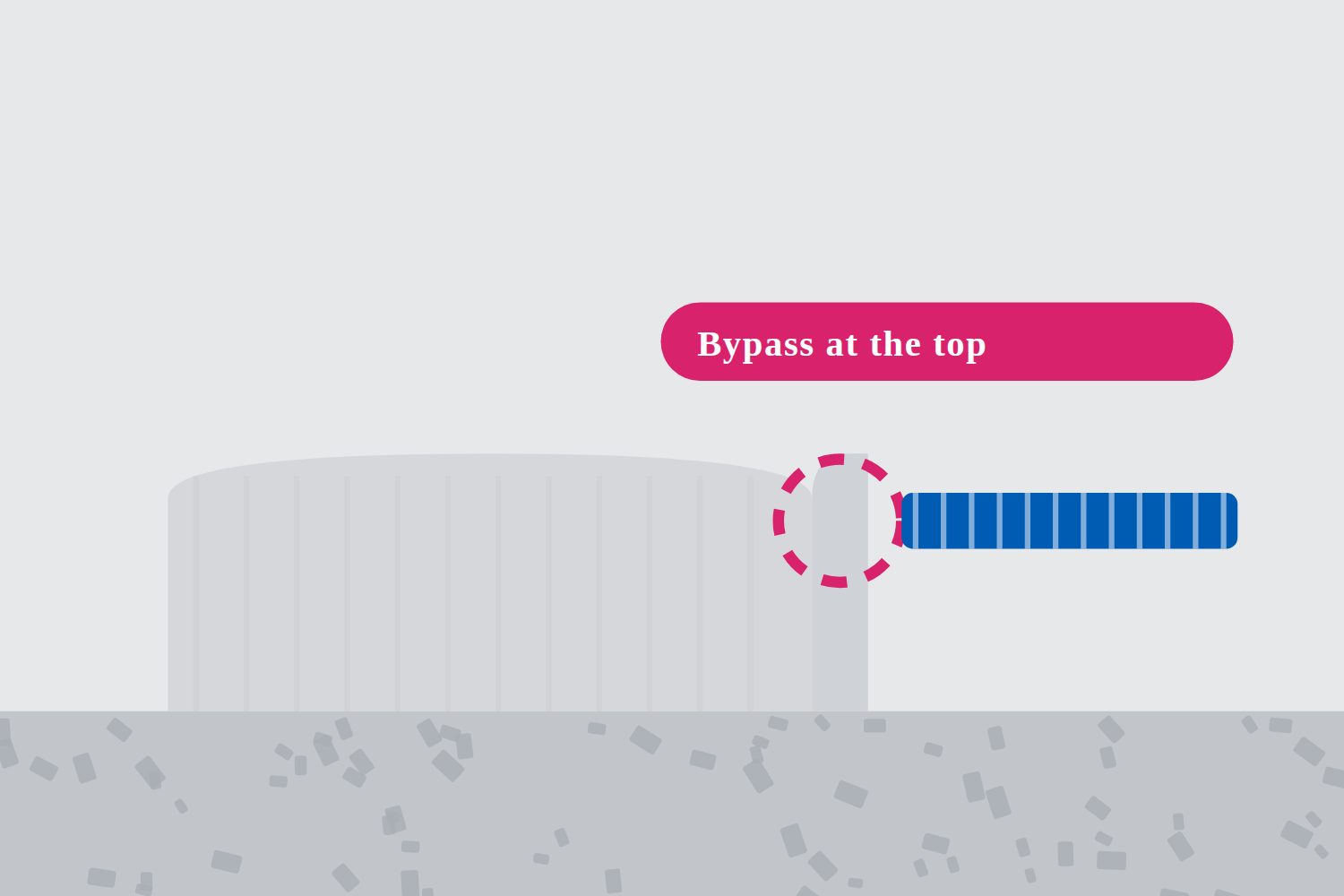
  • The end cap at the far end is cut to receive the overflow bypass pipe at the top of the end cap.
  • Top, not bottom: the bypass only takes flow once the tank is full, which is the opposite of the inlet.
  • The end cap is then placed to close off the Separator Row.
Non-woven geotextile being laid over the full length of a completed Separator Row

The Separator Row

Cover the Separator Row

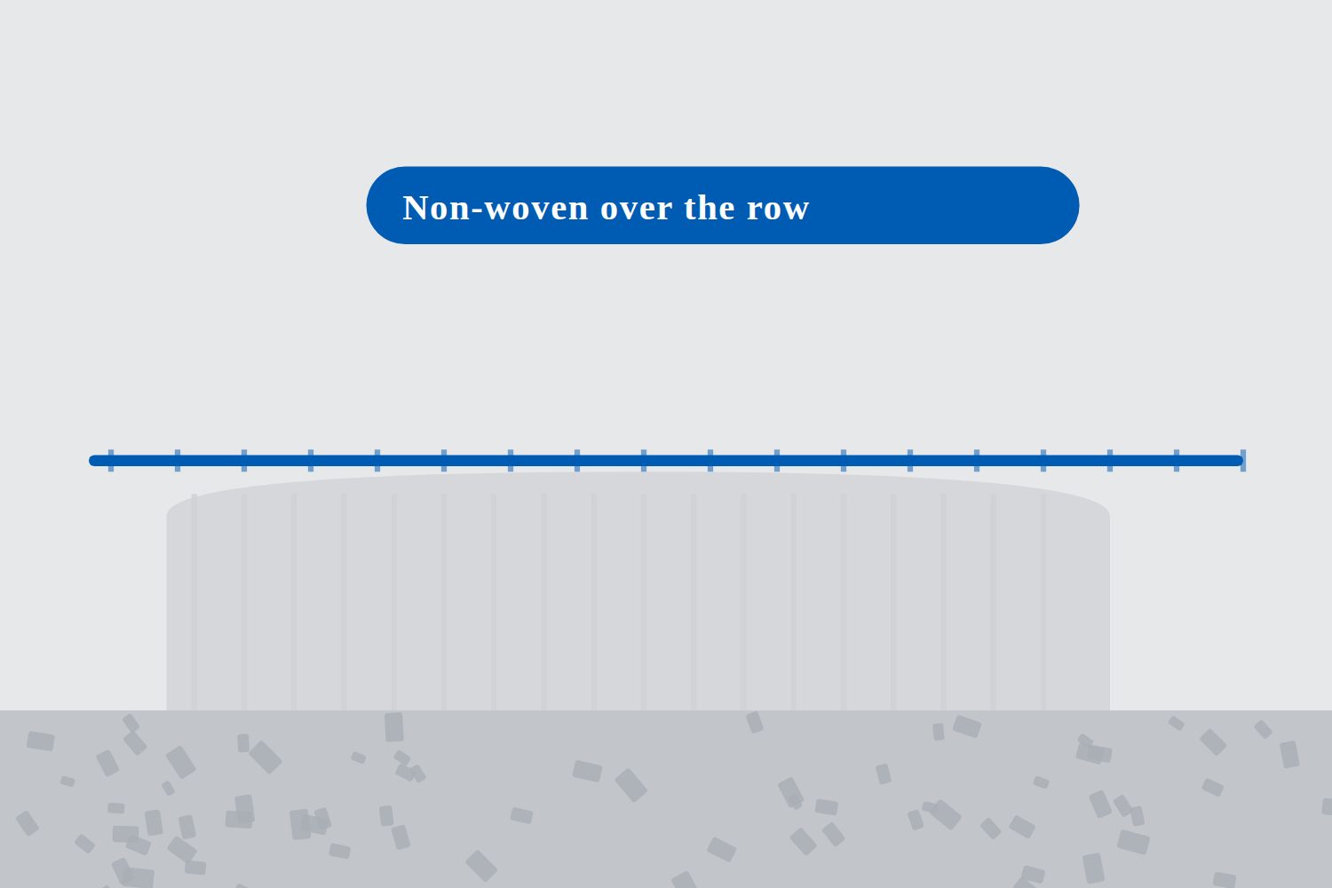
  • A layer of non-woven geotextile is placed over the entire length of the Separator Row.
  • Non-woven over the top; woven underneath. The two do different jobs and are not interchangeable.
  • Entire length means end cap to end cap, with no gaps left open to the stone above.

The Separator Row · Question 11 of 20

How far must the woven geotextile extend beyond the Separator Row chambers and end caps?

The Separator Row · Question 12 of 20

Where should the invert of the inlet hole be cut in the end cap?

The Separator Row · Question 13 of 20

How do two chambers connect to each other?

The Separator Row · Question 14 of 20

What goes over the completed Separator Row?

Several completed chamber rows running parallel across the tank bed

Building out the tank

The remaining rows

  • By connecting adjacent chambers, build out the remaining rows.
  • The same connection applies throughout: direction guides followed, large corrugations over small, locating buttons home.
  • Then cap off all rows with an end cap.
Bypass pipework being assembled between rows at the end of the tank

Building out the tank

Overflow bypasses

  • Cut-outs for overflow bypasses should be made, and bypass pipes assembled and connected.
  • Make the cut-outs to the drawings for your tank: the bypass arrangement is part of the hydraulic design, not a site detail.
  • Check every connection before the stone goes near it.
A cross-section showing stone columns between chamber rows carrying load

Building out the tank

Spacing is structural

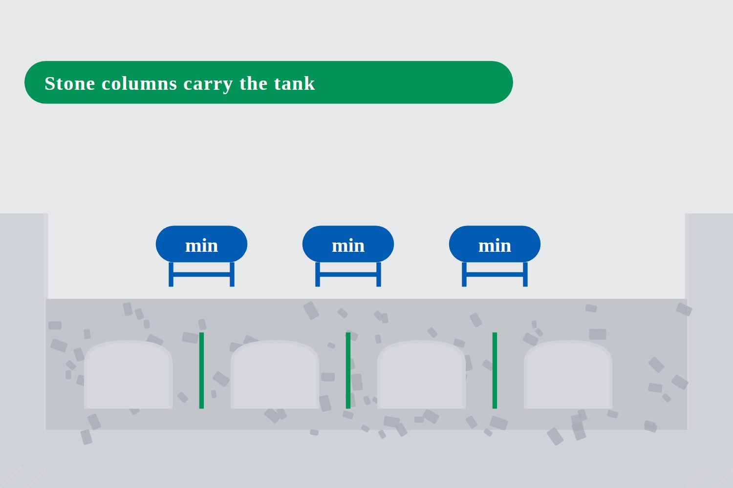
  • Take care to ensure that the spacing between rows matches the design.
  • The stone columns between chamber rows form an essential part of the overall structure. It is therefore essential for the structural integrity of the tank that, in all cases, at least the minimum required separation between chambers is achieved or exceeded.
  • Similarly, the correct spacing between the edges of rows and the side walls of the excavation must be ensured.

The gaps between the rows are not spare ground. They are columns, and they carry the tank.

Building out the tank · Question 15 of 20

Why does the spacing between chamber rows matter so much?

Building out the tank · Question 16 of 20

The rows are built slightly closer together than the design shows, to fit within the excavation. Is that acceptable?

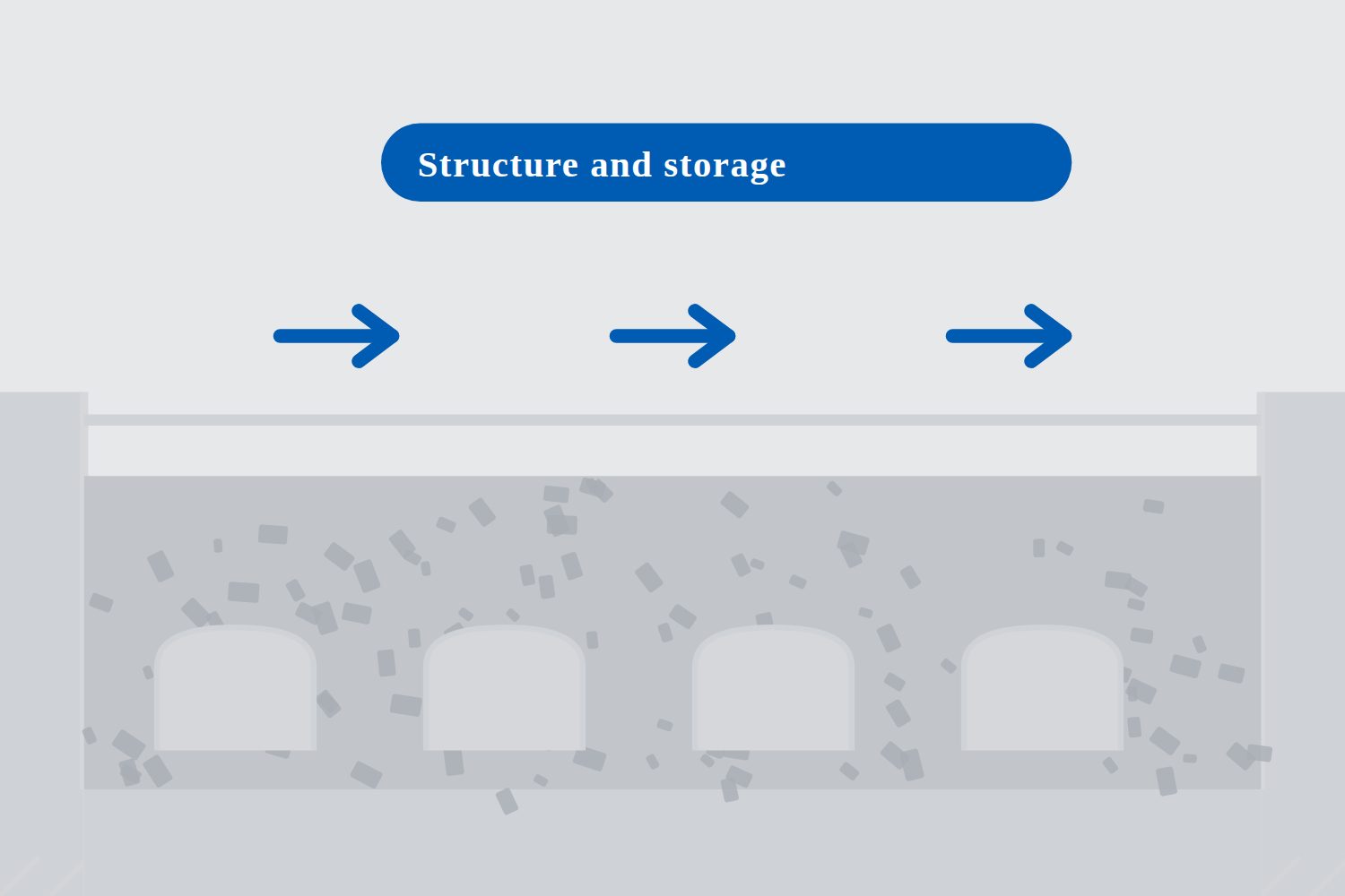
A cutaway of chambers surrounded by angular stone, with load arrows through it

Stone fill around the chambers

Why this stone matters

  • Only clean, crushed, angular stone may be used within the tank. It should conform to Clause 505 Type B, or Remblai 20-40 specification.
  • The stone around the chambers provides a critical function for both the structural and the hydraulic performance of the tank.
  • It is therefore essential to adhere to these guidelines for stone placement. Failure to do so may result in underperformance, damage or failure of the tank.
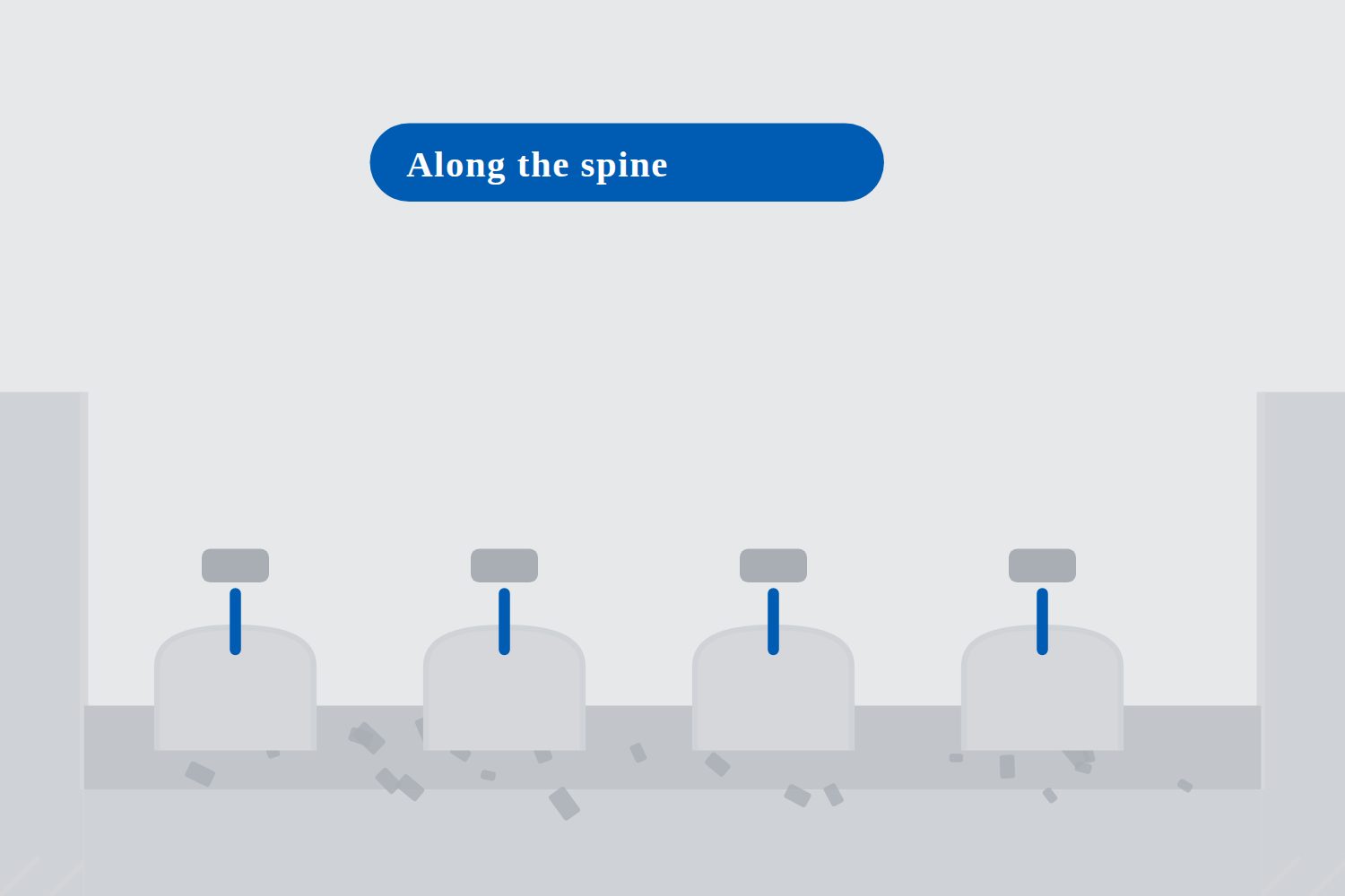
Stone being placed along the spine of a row and dropping between rows

Stone fill around the chambers

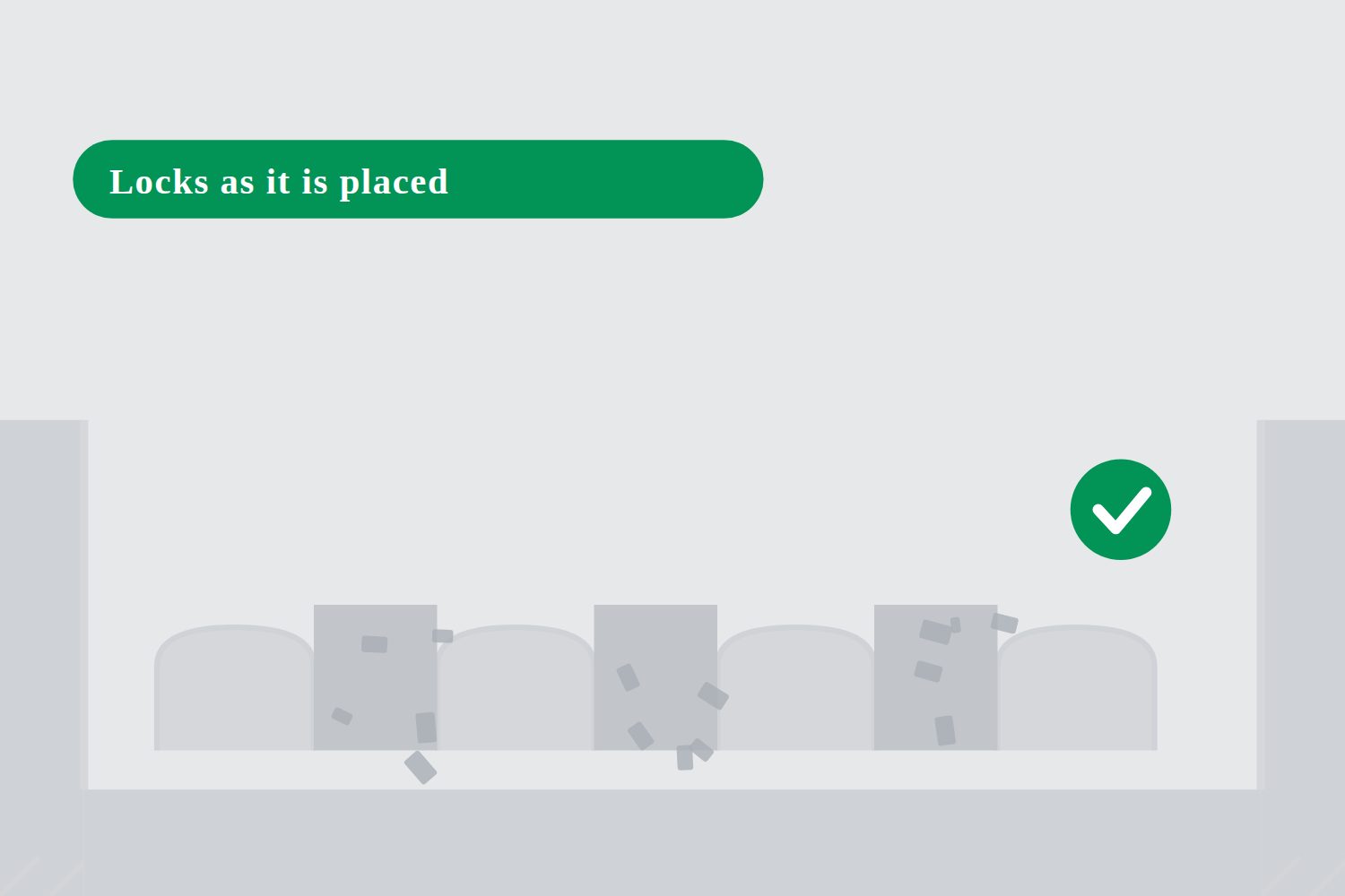
Lock the chambers in

  • Place the initial fill stone carefully along the spine of each row, allowing it to drop between rows.
  • This locks the chambers in place and prevents movement during filling.
  • Until the chambers are locked in, anything placed against one side can push it off line.
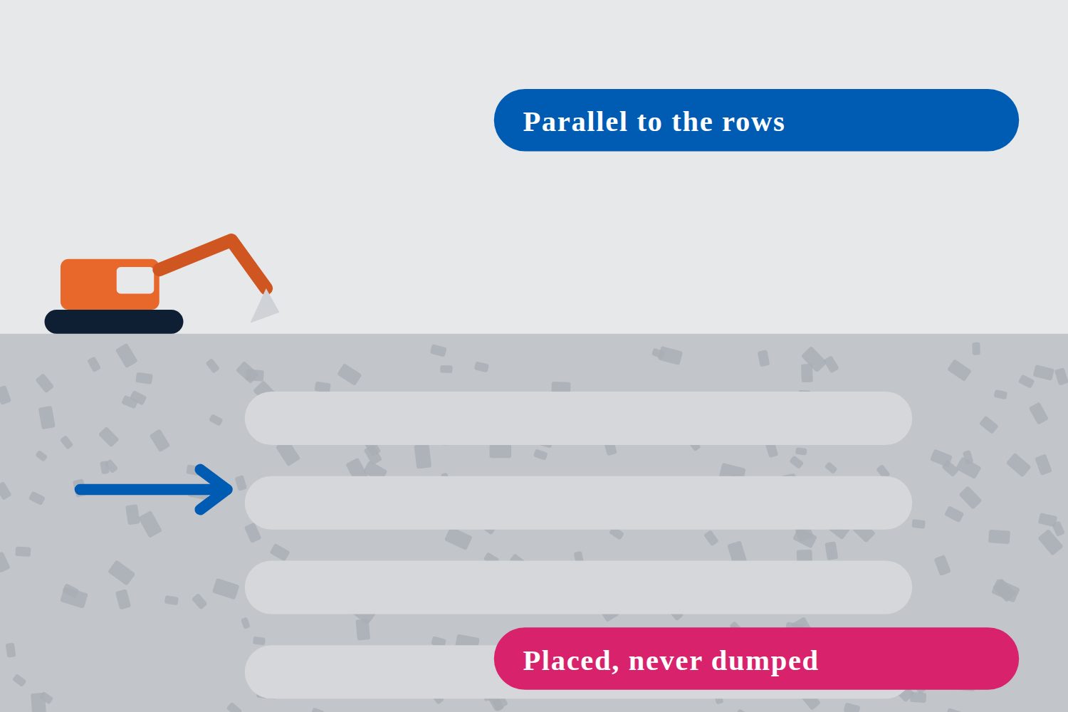
A machine placing stone from the end of the excavation, working parallel to the rows

Stone fill around the chambers

Fill from the ends

  • Once the chambers are locked in, place the fill stone from the ends of the tank excavation.
  • Filling must proceed parallel to the rows.
  • Stone must only be placed, never dumped, on top of the tank.

Placed, not dumped. A dropped load arrives as an impact, not as fill.

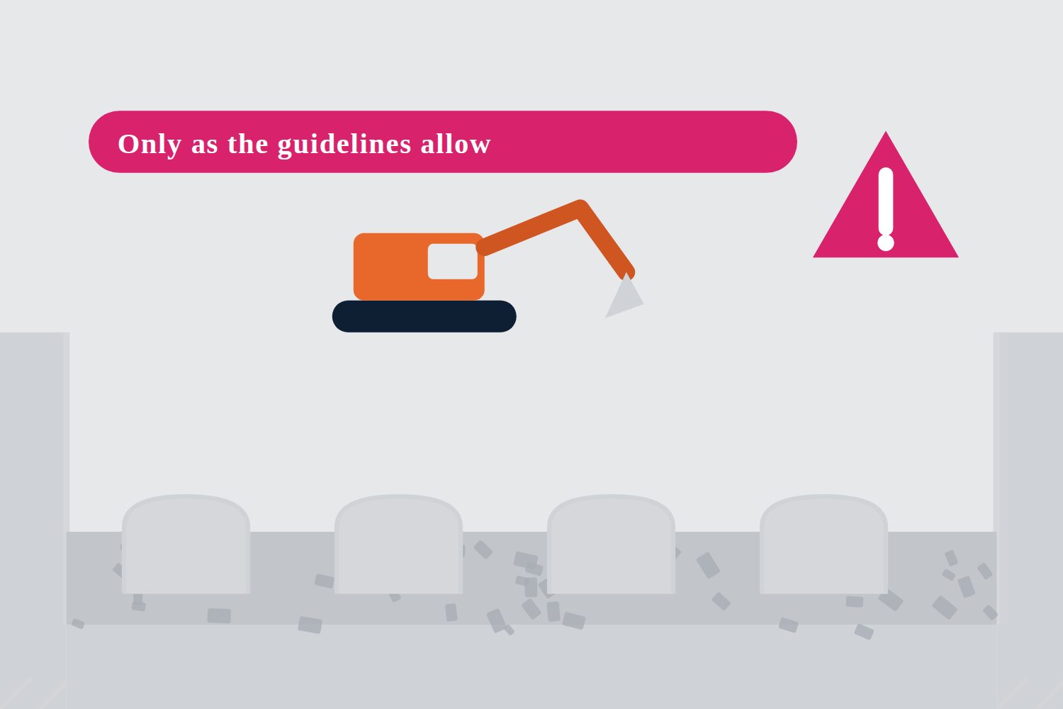
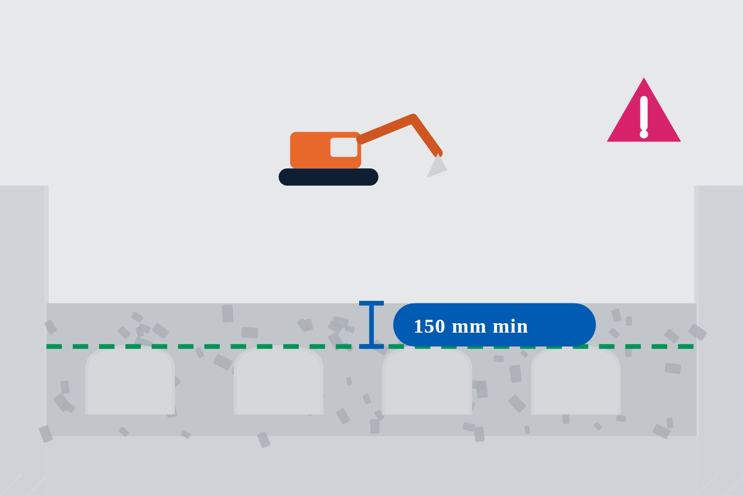
A warning sign over a machine working above a partly filled tank

Stone fill around the chambers

Warning: plant above the chambers

  • Equipment may only operate above the chambers strictly as per the guidelines.
  • Those guidelines are set out later in this section and in Table 2 of the RainSafe Installation Guide.
  • Until the stated minimum cover has been reached, mechanical equipment has no business on top of the tank.
Even fill either side of a chamber beside uneven fill pushing one over

Stone fill around the chambers

Keep it balanced

  • When placing stone, ensure that backfill around the chambers is placed evenly, to avoid exerting unbalanced, excessive lateral loading on the chambers.
  • Stone heaped against one side of a row and not the other pushes the row sideways.
  • That could cause displacement, or compromise the structural capacity of the completed tank.
Adjacent rows being brought up together, with the level difference marked

Stone fill around the chambers

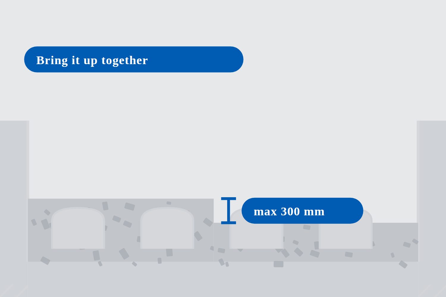
The 300 millimetre level rule

  • Stone fill between chamber rows and at the edges of the tank must be brought up evenly with the rest of the tank.
  • Ensure that the difference in levels from one row to the next never exceeds 300 millimetres.
  • Bring the whole tank up together rather than completing one bay at a time.

Never more than 300 millimetres of difference between one row and the next.

Angular stone shown locking together between two chamber rows

Stone fill around the chambers

Compaction between the rows

  • It is not necessary to compact stone between the chamber rows.
  • Angular stone placed carefully locks as it is placed. That is what the specification is for.
  • Running plant over the tank to compact it is a far bigger risk than leaving it as placed.
A marked 150 millimetre layer of stone over the top of the chambers

Stone fill around the chambers

Warning: 150 millimetres of cover

  • Mechanical equipment may only be permitted above the tank once a minimum cover of 150 millimetres over the top of the chambers has been reached.
  • Even then, only strictly in accordance with the instructions in Table 2 of the RainSafe Installation Guide. That guidance is based on vehicle and axle weights.
  • It is important to avoid excessive forces resulting from sudden acceleration or deceleration when manoeuvring above the tank.

No plant on the tank below 150 millimetres of cover. Above it, only what Table 2 allows.

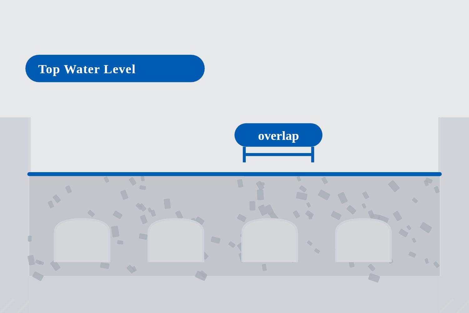
Woven geotextile being lapped across the top of the filled tank

Stone fill around the chambers

Geotextile at Top Water Level

  • Once the fill stone reaches Top Water Level, woven geotextile is to be placed over the tank.
  • Minimum overlaps are required between adjacent strips, and with the side-wall geotextile.
  • Check the laps before the cover material goes on. This is the last chance to see them.

Stone fill around the chambers · Question 17 of 20

When may mechanical equipment operate above the tank?

Stone fill around the chambers · Question 18 of 20

What is the maximum difference in fill level allowed from one row to the next?

Stone fill around the chambers · Question 19 of 20

Which statement about stone around the chambers is correct?

A finished surface above a completed tank, shown in cutaway

Finishing up

What good practice protects

  • Following these guidelines ensures optimal performance and the structural integrity of your tank.
  • Every rule in this module protects one of two things: the structure that carries the load above, or the voids that store and move the water.
  • Both are set during installation and neither can be adjusted afterwards.
A completed installation record being signed off on site

Finishing up

Records and certification

  • The record that installers and machine operators are familiar with the guidelines and agree to follow them is part of the tank being certified.
  • Keep it with the project records, along with the drawings the tank was built to and any deviation approved by CubicM3.
  • If something was approved as a deviation, the approval belongs in the file beside the record.
A site crew at the end of a completed installation

Finishing up

Everyone’s responsibility

  • Thank you for taking the time to learn about the installation process for your RainSafe stormwater management system.
  • Most of what goes wrong with a buried tank is decided by people who were doing their best with the wrong instruction.
  • Remember, safety and compliance are everyone’s responsibility.

Finishing up · Question 20 of 20

What does the installers’ and operators’ record of familiarity with the guidelines support?

Your score

0 / 20

    Sample module for demonstration, built from the RainSafe installation narration script. It does not replace the RainSafe Installation Guide, the CSTB-ATec document or the pre-installation briefing, and any deviation from these steps must be approved by CubicM3.